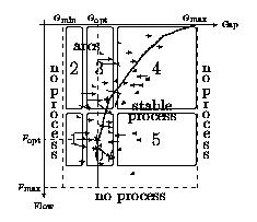
Figure 3: State space of the EDM process and control actions predicted by the induced model.
| Application domain: | Electrical Discharge Machining |
| Further specification: | Six data sets |
| Pointers: | Contact Aram Karalic Aram.Karalic@ijs.si |
| Data complexity: | 67-155 examples |
| Data format: | Prolog |
Some parameters can be controlled during the process (gap, flow), some require process interruption (duration of discharges, ...), and some of them are inherent to the particular machining task. For a standard set of workpiece types there exist predefined sets of values for the process parameters which guarantee a certain degree of generated surface quality. However, the settings are very conservative and do not yield really good performance in terms of the time needed to accomplish the task. Therefore, a human operator is normally employed to control the process parameters and minimize machining time. Our task in this domain was to model the operator's behavior.
To enable detection of the rate of change of attributes, the predicate ``<'' was defined as the background knowledge.
Since we tried to model control by two variables (gap and flow) the learning task was decomposed into two separate learning tasks -- learning gap control and learning flow control. For each control variable three actions were possible: increase the variable (the action was assigned a numerical value +1.0), no action (0.0), and decrease the variable (-1.0).
    f(DG,ASM,ASD,BSM,BSD,CSM,CSD,ISM,ISD,
         ALM,ALD,BLM,BLD,CLM,CLD,ILM,ILD) :-
                 ILD >= 0.55, DG is 0.3,!.
    f(DG,...) :- CLM >= 5.6300, DG is 0.7,!.
    f(DG,...) :- BSM =< 1.1000, DG is -0.2,!.
    f(DG,...) :- DG is -0.5,!.

    f(DF,...) :- ASD =< 0.0100, DF is 0.0,!.
    f(DF,...) :- ALD =< 0.0800, DF is 0.0,!.
    f(DF,...) :- ASM < ALM, ISD < ILD, BSD < BLD,
                 DF is 0.1,!.
    f(DF,...) :- BLM < BSM, DF is 0.5,!.
    f(DF,...) :- DF is 0.1,!.
DG means change of gap while DF means change of flow. Operator's and expert's comments on the model were that most of the described actions were logical, but there were some remarks about understandability of the models:
The above procedure resulted in a model consisting of 20 ``disjunctive'' clauses, each predicting gap and flow actions. As an illustration we present the clause constructed from the last clause of the ``gap'' submodel and the last clause of the ``flow'' submodel:
    f(DG/DF,...) :-
        ILD  < 0.55, CLM  < 5.63, BSM  > 1.10,
        ASD  > 0.01, ALD  > 0.08, ASM >= ALM,
        ISD >= ILD,  BSD >= BLD, BLM > BSM,
        DG is -0.5, DF is 0.1,!.
Despite the fact that the new model contained more than two times as much clauses as the original and that all the clauses were larger, the operator and the expert claimed that this model is more comprehensible than the first one.
The domain expert qualitatively defined the relation between the effectiveness of the process and the control parameters -- gap and flow. The state of the process is presented in two dimensions on Figure 2. The diagram defines two states of the process: stable state and arcing state. The goal of the control is to guide the process as close as possible to the boundary between the arcing and the stable region. Additionally, there is a boundary region (marked with an asterisk) that represents the region of the best process performance. The diagram was further divided into six regions, representing qualitatively different process behaviors.
The model was evaluated by plotting suggested actions into the state diagram of the process. For each rule in the model, at least one vector representing the combination of the suggested gap and flow actions was drawn, representing the suggested action. For some rules more than one vector was drawn, because very general rules could cover more than one region of the state diagram. Figure 3 depicts actions suggested by the induced model.
Figure 3: State space of the EDM process and control
actions predicted by the induced model.
One can immediately see that most of the vectors point towards the boundary between the regions -- the optimal working region. Additionally we see that many of them point towards the point of optimal performance. It seems that the model is correctly modeling the operator's performance.